|
Gerðt 040 and Gerðt 041 - History |
Munitionsschlepper
for Karlgerðt
In October
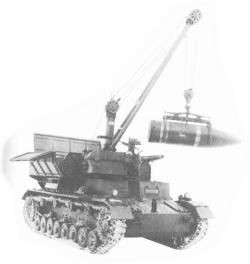
1939, the Rheinmetall-Borsig project to design a Munitionsschlepper was
authorized. The Munitionsschlepper with the electrically driven Wippkran
was to deliver the shells with associated charges and cartridge casings to
firing position. The chassis, obtained from the Pz.Kpfw.IV production
series, carried the superstructure with electric Wippkran, ammunition box
for four shells, with crew seats mounted at the rear. Electrical power for
the Wippkran was provided by the same 2-cylinder gasoline motor/generator
set used in a normal Pz.Kpfw.IV to drive the electrical motor for turret
traverse. The longest reach of the Wippkran arm was selected, so that a
shell could directed transferred from the Munitionsschlepper to the
loading tray on the Gerðt 040 while in its firing position. The shell
were picked up by a special shell gripper which was stowed on the right
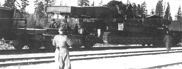
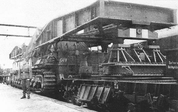
front of the Munitionsschlepper. During rail transport or when driving
under low overhead clearance, the Wippkran arm ws stowed across the top of
the ammunition box.
Another
extract from the book : Panzer Tract No.17
Gepanzerte Nachschub Fahrzeuge (Armored Supply/Ammunition Vehicles)
VK3.01 to schwere Wehrmacht-Schlepper
Created by Thomas L.Jentz/Hilary Louis Doyle
ISBN : 0-9744862-4-8
Page 17-30 to 17-36
Munitionsschlepper auf Panzer IV
Pz.Kpfw. IV Fgst. AUsf D, E, and F
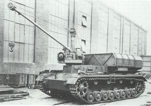
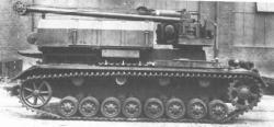
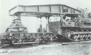
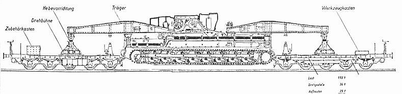
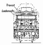
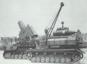
Munitionsschlepper description from the manual dated 15 April 1941 : The
Munitionsschlepper with the electric Wippktran is intended to transport
the shells with the associated charges and cartridge cases to the firing
position. The chassis supports the superstructure with the electric
Wippkran, the Munitionskasten (ammunition bin) with crew seat, and the
charges for four shells. Inside the vehicle are four holders for the
charges and four cartridge cases. The longest reach of the Wippkran was
chosen so that shells could be loaded onto to the mortar's loading
carriage directly from the munitionsschlepper at the firing position. The
shells are clamped in a special Geschossgreifer (Shell gripper) that is
stowed on the right front of the vehicle. A sail cloth cover protects the
Geschossgreifer from dust and dirt.
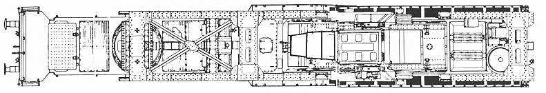
The series produced normal Pz.Kpfw. IV Fahrgestell is utilized as the
chassis for the munitionsschlepper. In the roof of the superstructure is
an opening for the driver's hatch and beside it an opening for access to
the charge holders. Two adjustable vision posts are located on the front
and left side for the driver to see out.
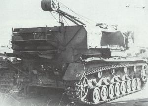
Radiators and cooling air fans are suspended from the rear engine deck and
can be removed and installed through hatches located on the rear deck.
Special openings in the deck are intended for refilling cooling water and
fuel for the DKW-Motor. A foot rest for the crew is located on the rear
wall.
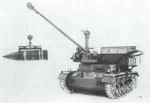
The highest load capacity for the Wippkran is 2500 kg at the longest boom
extension of 3.4 meters. The DKW-Motor/Generator set supplies electrical
power for the Wippkran.
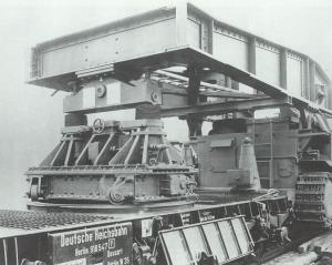
The munitionskasten (ammunition bin) protects the shells. The forward wall
can be removed for easier access to manipulate the shells into place. The
Munitionskasten consists of a rear bin with hinged lid, a removable front
wall, a four part hinged top, and two hinged side walls with limited
opening. Two spacing pipes with fasteners connect the front wall to the
rear bin. Four fastening bands hold the shells in their beds. A crew seat
for three men and a travel lock for the Wippkran boom are located on the
rear wall.
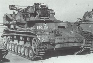
This 25 metric ton Munitionsschlepper was manned by a crew of four; two
Fahrer (drivers) and 2 Begleiter (assistants). By 1942, a second lighter
shell has been produced for the 60cm Karl Geraet requiring a different
Greifer uer leichtes Geschoss which was transported on a truck. Later in
1944, two additional shell grippers (one Greifer fuer leichter Geschoss
and one Greifer fuer schwerer Geschoss) were needed for the 54cm shells
produced for the Geraet 041 (refer to Bertha 's Big Brother, Karl Geraet
(60cm) & (54cm) from Panzer Tracts). Also, the ammunition stowage on
the Munitionsschlepper had to be modified to transport 54cm shells for the
Geraet 041.
A total of 13 Munitionsschlepper were produced on Pz.Kpfw. IV Ausf D, E
and F chassis which has been acquired from the normal Pz.Kpfw. IV
production run as reported in May 1941. There were two Munitionsschlepper
for each of the six Geraet 040 Nr. I to VI and one for the experimental
Geraet Nr. VII. The status of the Munitionsschlepper was reported on 29
September 1944 as 13 available of which six were with Batterie 428 and
638, two for the Waffenamt (configured for 040), two converted for 041,
and two ready for issue. |
|